As I predicted, I didn’t like the first attempt at parts placement. Conceptually, it seemed ideal to put the parts for each appendage at the corresponding angle. However, there are some problems with this in practice. As best as I can tell, being a novice at KiCAD, routing a bunch of parts at odd angles was going to be a headache. But mainly, it just looked ugly. Maybe if there were 8 identical arms I would have thought differently. But I decided to toss the angled layout and go with a more traditional placement where parts are lined up either vertically or horizontally, that is, 90 degree angles all around. The only exception being the edge connectors themselves.
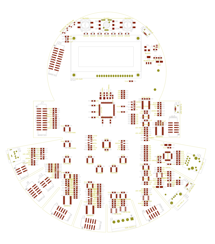
When I was done, one thing I notice is how much area is consumed by discretes, and my earlier design decision to stick with 0805 SMT chip packages throughout. The idea was to make hand assembly easier for hobbyists. I’ve already bent those rules a little, but using quite a few QFP packages. I would actually switch all to 0603 if it would make the board smaller. But truth is, the board size is almost fixed by two parts: the RS-422/485 serial terminal block connector and the SD CARD socket (underneath the two USB ports). Those two parts dictate the 220mm diameter of the tail sector containing the 8 legs. And that in turn loosely sets the diameter of the head, in order for the squid to be roughly proportional, not to mention there has to be room for the LCD character display. Unless I run into a serious problem with routing or production, I’m sticking with this size for now. With one exception: note the horizontal line at the top of his head. I’m giving him a flat head approximately as shown.
Making allowances for the new (to me) tool, I’m expecting the routing to be fairly easy. To start with, this is a four layer board, so for the most part power and ground will be straightforward. I spent a lot of time with parts placement, as I usually do, trying to make the smartest possible choices, taking into account both the electrical performance issues as well as routing. I think most engineers will agree that this is almost an art rather than science. Different engineers might come up with different arrangements, but any well-placed board layout will be a breeze to route, either by hand or the auto-router. For the moment, I’m planning to hand-route this board. I think my placement is good enough that hand routing will probably be quicker than the added step of learning yet another new tool, the KiCAD auto-router.
CHANGES DRAFT2:
- changed PS/2 connector from straight to right-angle.
- Shuffled the placement of the SD Card socket and the USB connectors opposite. I’m worried about trimming the thru-hole pins of the Type A USB connector close enough to the PCB. If not trimmed close enough, the will interfere with inserting the SD Card. If trimmed TOO close, the USB connector might not make good mechanical or electrical connection to the board.
- Repositioned all components be vertical or horizontally aligned.