A friend of mine recently asked if I could help him repair a kit he had assembled. This device is used on model railroad layouts, on a siding, for example, to automatically slowdown and stop the train, wait for a period of time, and then start back up again. The idea is to simulate a train stopping for passengers.
I had tinkered with N-gauge model railroads in the past, and this sounded like a simple and fun little project to help him out. Also, I had just reassembled my laboratory after being in storage for over a year, so this was also a chance to make sure everything was unpacked and working.
My friend’s layout uses the old analog system of control. There is no PWM (pulse-width modulated) speed control. There is no DCC digital control. Only simple, 40-plus-years-old analog voltage, 0 to 12VDC speed control. As a result, this device was just a few transistors and looked quite simple to understand and fix.
The product is the Train stop switch, P/N 199311 from Conrad Electronic in Hirschau, Germany. They sell this as a kit, as my friend purchased it, and also as a pre-assembled unit.
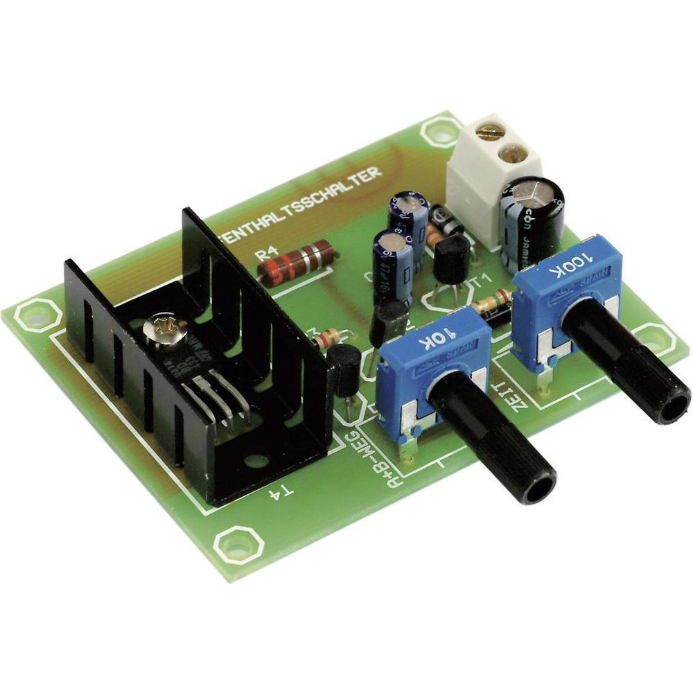
I first inspected the boards, and immediately saw a few solder joints which were the obvious cause of the problem. But, I wanted to understand how this circuit worked, and hopefully have a way to test it myself, not having a model railroad at my disposal. I learned a lot.