So, how does this thing work? Not exactly as I first guessed:
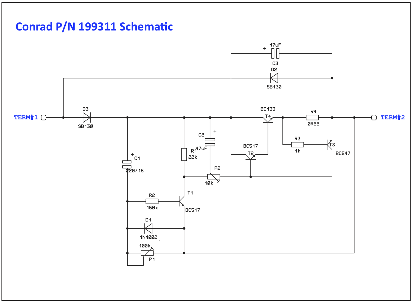 Schematic from Conrad
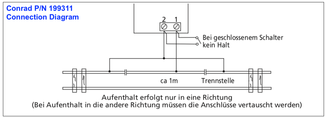 Connection Diagram
The first thing I noticed was that there is no direct ground connection. Term#1 connects to the train power pack, nominally 12 VDC at full speed, and Term#2 connects to the isolated section of track being controlled.
Obviously this circuit depends on the load of the train’s engine, and my first attempts to model the engine as a simple resistor failed. It turns out that this circuit depends on the various characteristics of the DC motor in the model train engine. Each engine can behave differently, based on it’s characteristics.
I didn’t have an engine or motor to test with, so I relied on the internet. Some sites discussing model train engines can be found here and here. And I found this app note on Spice simulation of a similar miniature DC motor from Precision Microdrives:
Here is the Spice model I ended up with:
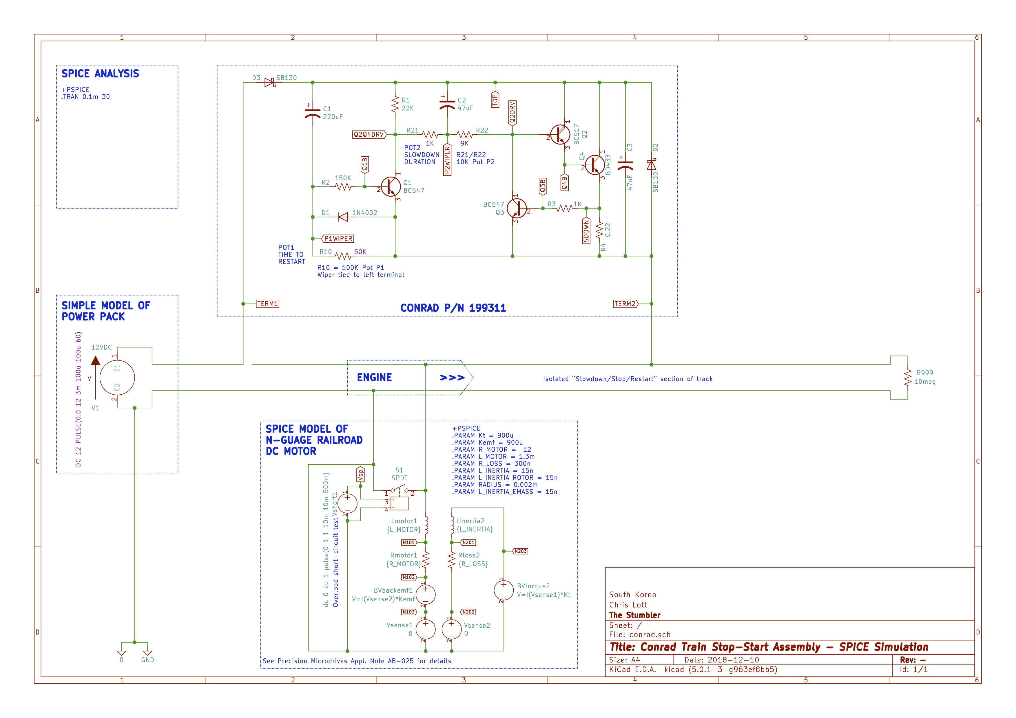 Spice Schematic
This circuit includes the Conrad controller, a model for the engine, and a small circuit to test the short-circuit overload protection feature of the controller.