Once again, referring to the schematic:
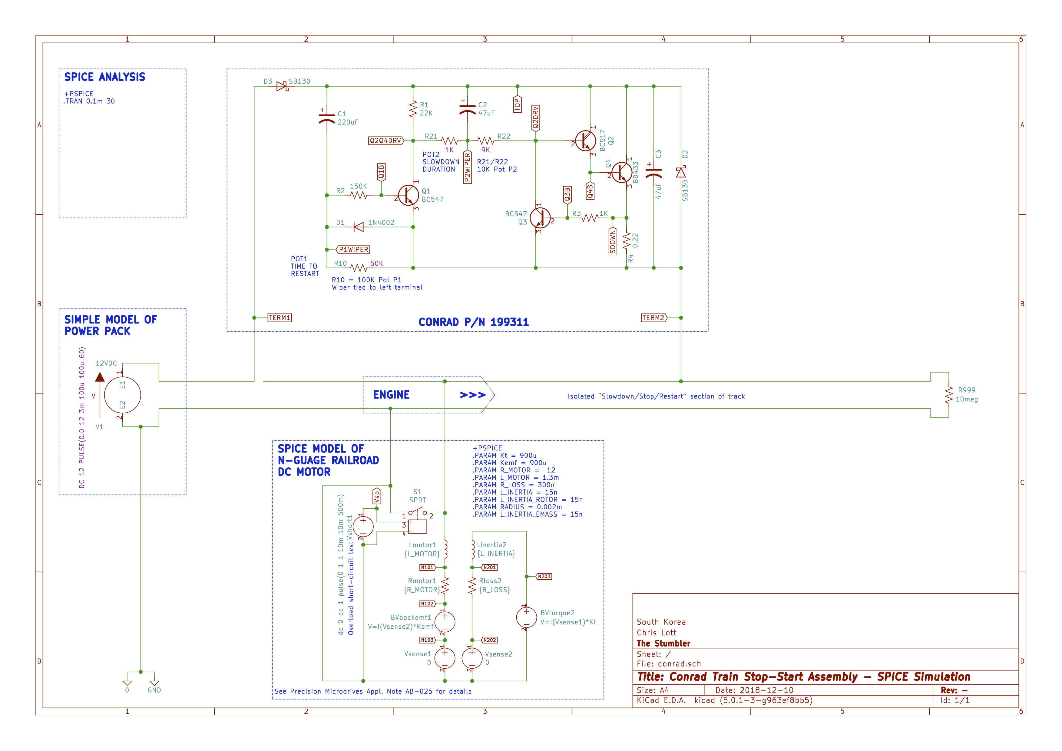 Spice Schematic
Not surprisingly, I was able to show by SPICE simulation that the controller works as designed. Specifically,
- Potentiometer P1 controls the delay to restart
- Potentiometer P2 controls the slowdown time
- Transistor Q3 functions as overload protector
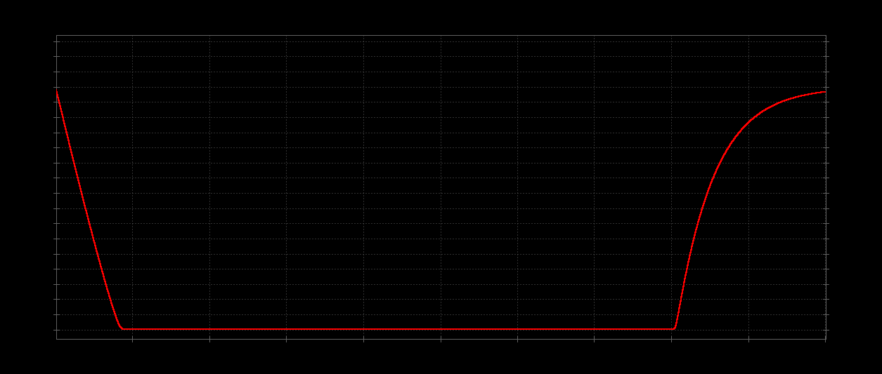
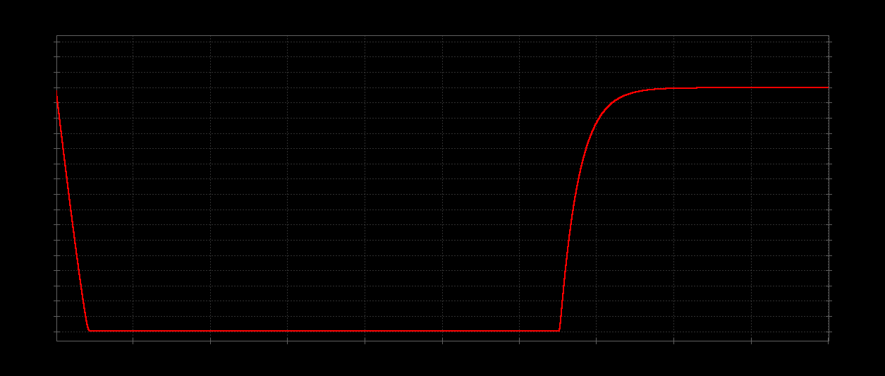
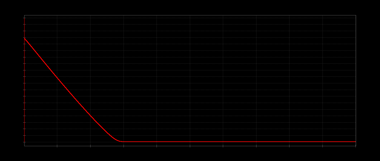
Here are some charts showing different timings vs. Potentiometer settings. Unfortunately, the print graph function didn’t print the axes values, so you’ll have to believe the values from my notebook.
 P1 setting 25% ( 25,000 ohms ), restart = 16 secs
 P1 setting 50% ( 50,000 ohms ), restart = 28 secs
 P1 setting 90% ( 100,000 ohms ), restart = 40 secs
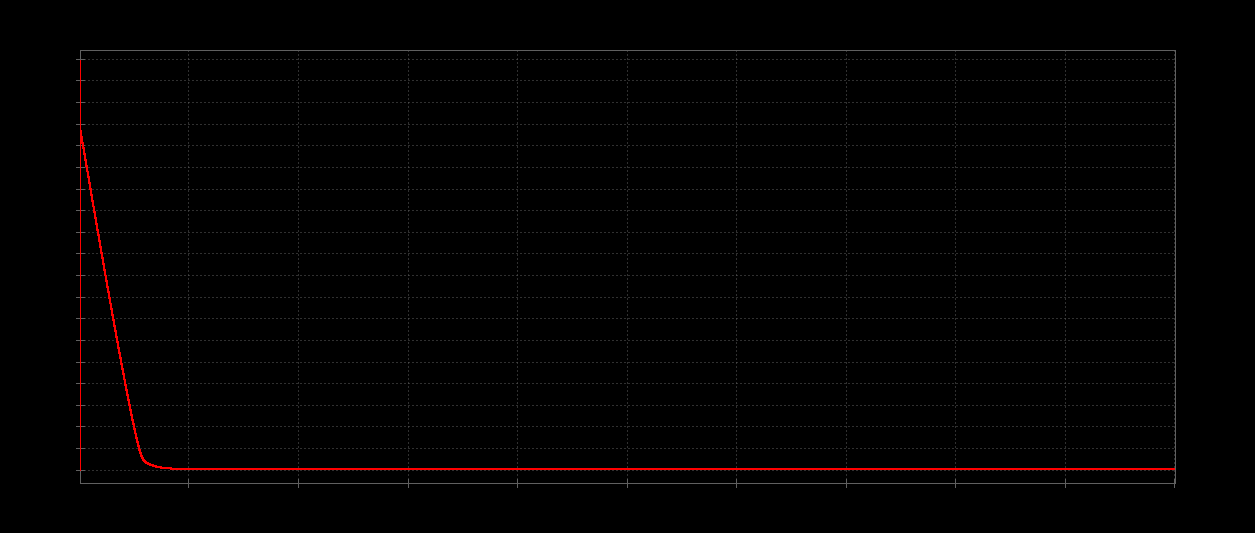 *P2 setting 10% (1000 ^ 9000 ohms ), slowdown = 0.5 secs *
 *P2 setting 50% (5000 ^ 5000 ohms ), slowdown not recorded *
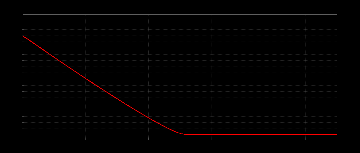 *P2 setting 90% (9000 ^ 1000 ohms ), slowdown = 2.5 secs *