Now that the new controller is up and running, there is one final item to consider - train detection. There are two methods commonly employed. One is a reed relay activated by a magnet mounted on the engine. The other is an infrared detector mounted under the tracks. My friend opted for the latter, and he got the Heathcote IRDOT units (pdf-manual).
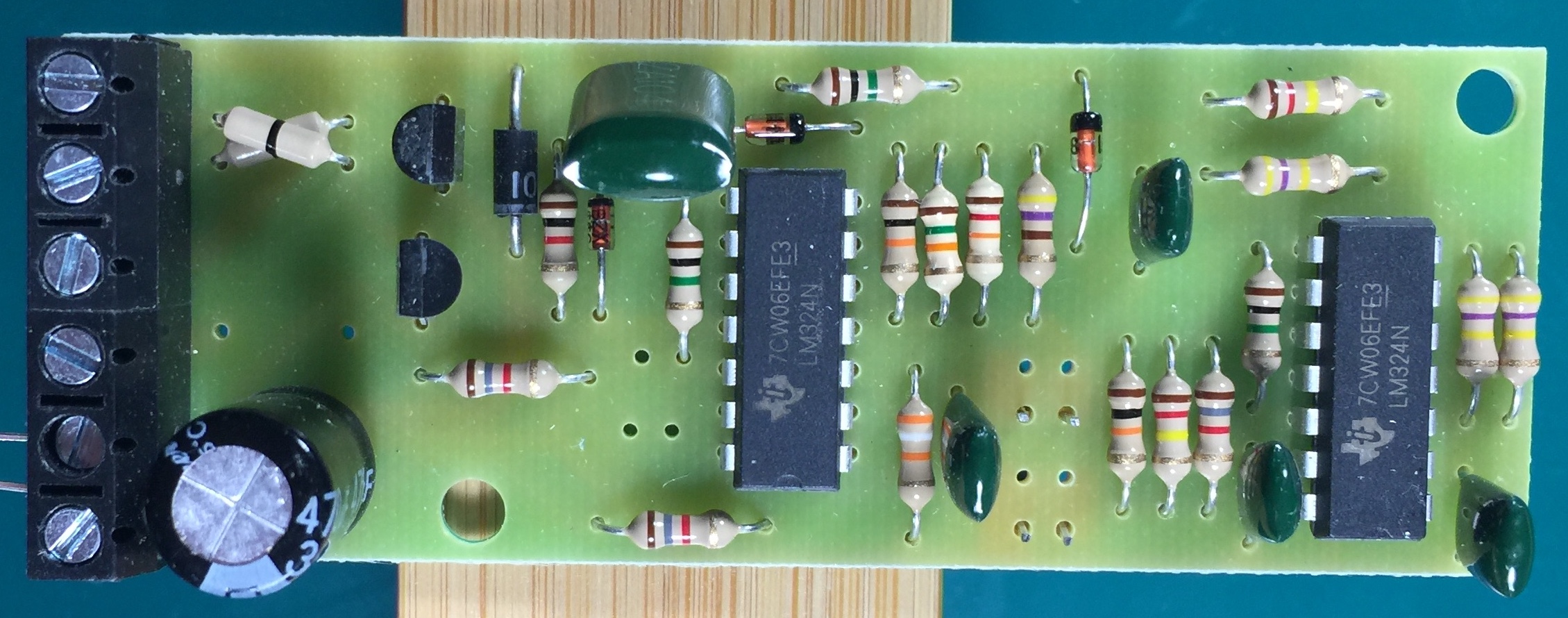 Heathcote IRDOT Train Detection Sensor
How do I know? Well, there was an installation issue. These come with the IR transmitter and receiver mounted directly on the circuit board. It is intended to be installed flush against the bottom of the model railroad base, as shown in this sketch:
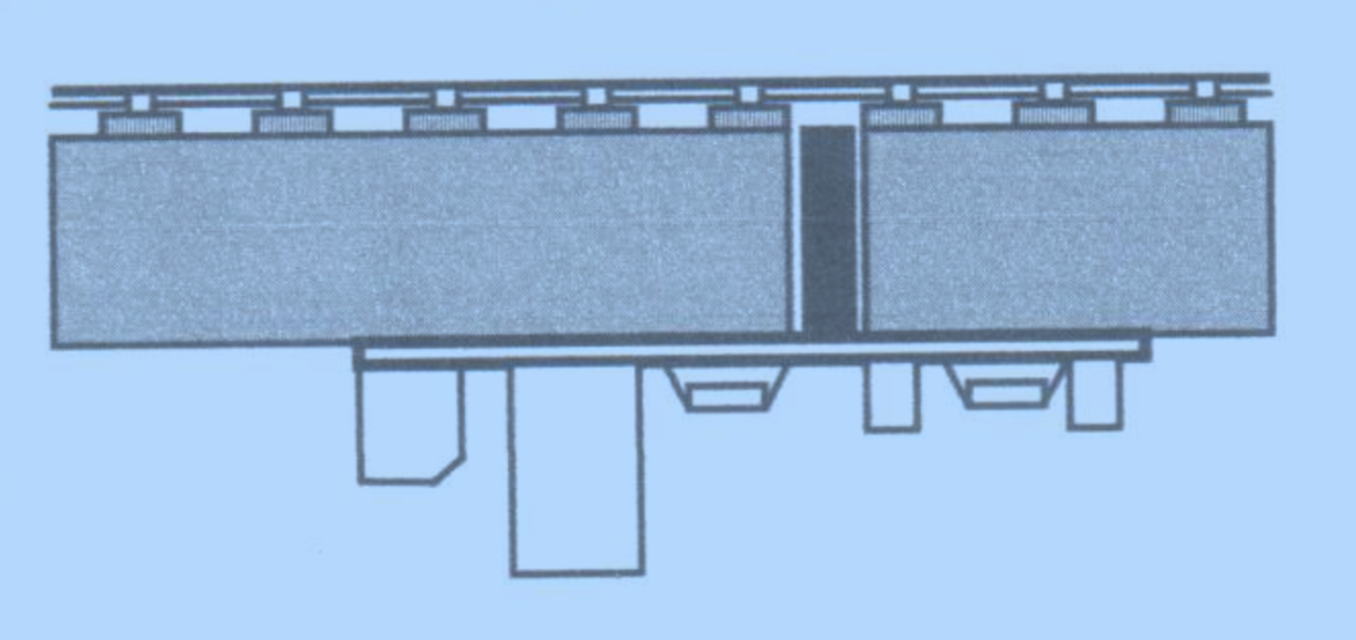 IRDOT Installation Sketch
In case the base is too thick, you have to remove them from the circuit board and install an extension cable (you can see the extension wires installed in the picture below). I agreed to help out, and add these extensions. In the process of doing that, I was curious how this thing worked. So I hooked it up on the bench for some probing.
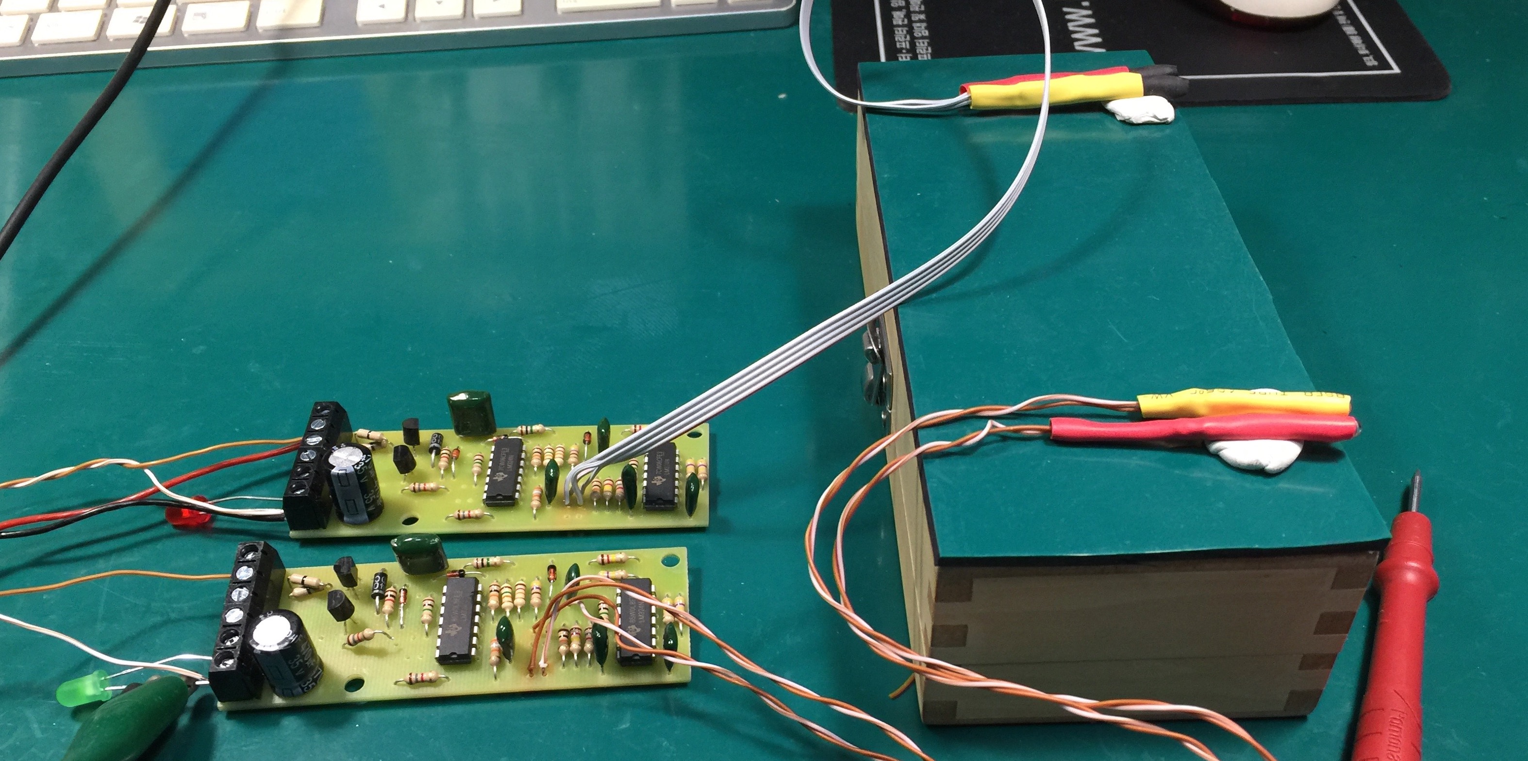 Lab Testing the IRDOTs
Theory of Operation
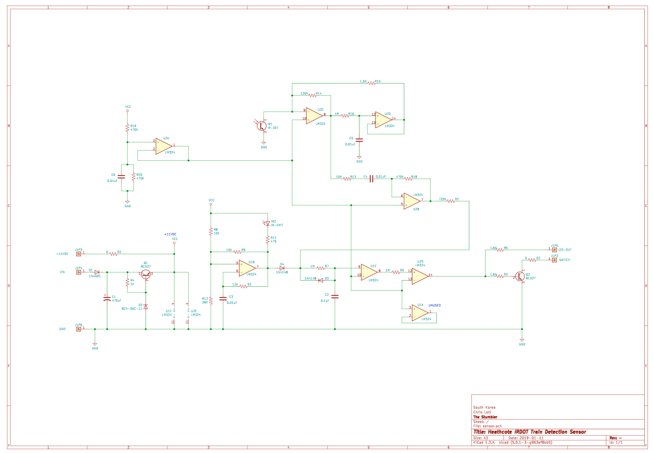 IRDOT Schematic
Semiconductors
The IRDOT has only a handful of semiconductor components:
- Transistor, NPN, BC337
- Diode, Zener 11V, BZX-55C-11
- Diode, Signal, 1N4148
- IC Analog, Quad op-amp (Texas Instruments LM324)
- Diode IR emitter, (Fairchild QEC112 or similar)
- Transistor IR detector, (Fairchild QSC112 or similar)
Power supply
The circuit of Q1 generates a regulated 11VDC signal. It operates in the standard emitter-follower, zener-controlled regulator configuration. The regulated voltage is used to power the op-amps, and is available off-board for accessories via pin #3.
Oscillator
Op-amp U1B forms a standard comparator-based relaxation oscillator My quick back-of-the-envelope calculation shows the oscillating frequency should be around 3.8 kHz. The actual measured frequency was 2.9 kHz. Close enough for this casual analysis.
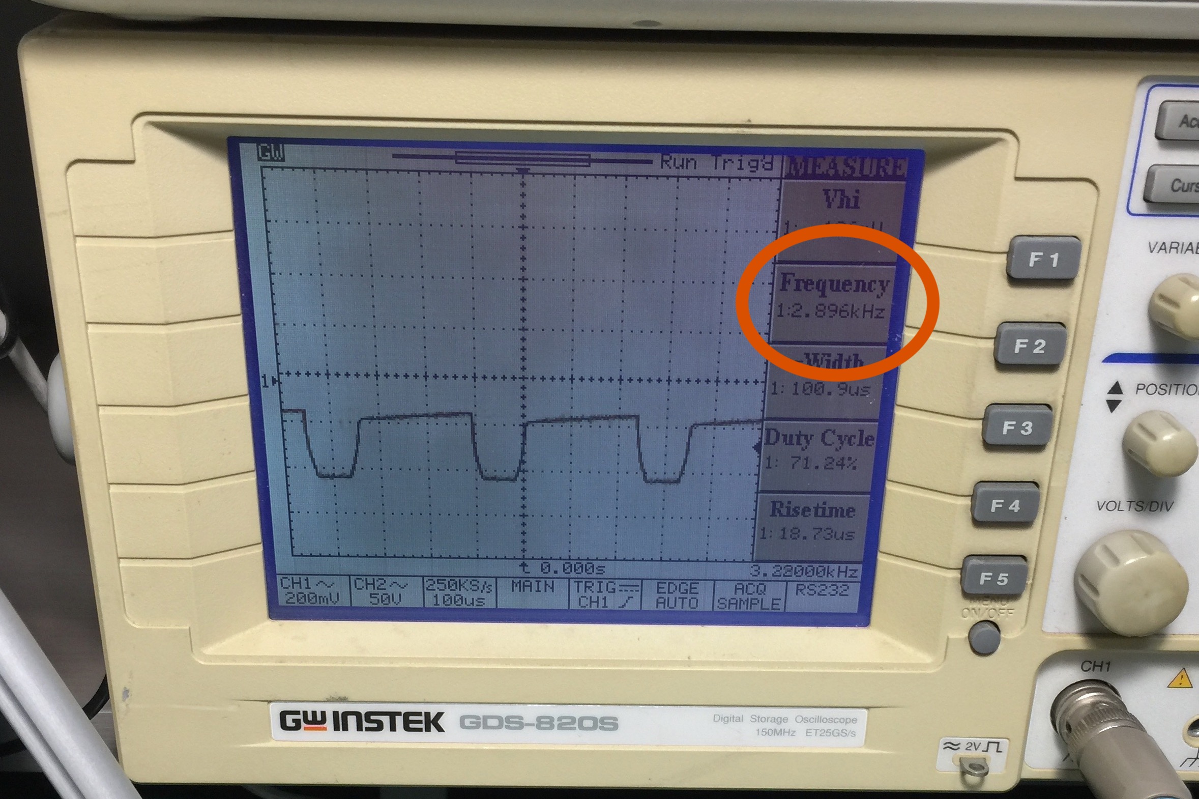 Measured U1B Oscillator Frequency
Virtual Ground
Op-amp U2A generates a virtual ground mid-way between ground and the regulated 11 VDC rail, using R19/R20 voltage divider and filter cap C6.
Preamp, AGC, and Integrator (incomplete)
Op-amp U2C acts as the IR sensor preamp. As a quick guess, it looks like U2D provides some kind of AGC, with a time constant set by R16 / C15. U2B is a high-pass filter. The pulses then build up a charge on integrating cap C2. Or, more accurately, remove charge from C2, since the pulses coming from U2B will be negative (wrt the virtual ground). When the IR emitter isn’t transmitting, a charge is built-up on C2 via D4/R7. (I haven’t measured this yet, I’m just guessing from eyeballing the schematic).
Detector and Output
U1C forms the detector, and U2D provides active high output buffering, and Q2 provides active low buffering.
Unused
Op-amp U1A is unused.