Asynchronous Serial
The old standby, asynchronous serial communication, is still widely used in embedded systems. The Serial Squid provides four serial ports, COM0, COM1, COM2, COM3. This number is arbitrary, and was simply chosen chosen to match the number of UARTs in the LPC1769. When designing a general purpose asynchronous interface, you have to consider a number of things:
- Direction (DTE/DCE)
- Signaling levels
- Handshaking signal(s)
- Connector type
- Space required
- Pinouts
Who Talks to Whom?
Slightly complicating things further is that one of these serial ports should be available for programming the LPC1769 chip. I have seen these chips get in a weird mode, where even JTAG can’t erase the chip. In those cases, serial port ISP is only way to recover. Based on this, the natural thing to do was make COM0 (LPC UART0) a DCE, so it can connect to a computer (DTE) with a straight-through cable for programming. Of course, when not involved in ISP serial programming, COM0 can be used by the application for any desired purpose. I envision most other uses of the serial ports will be as DTE, connecting to other embedded devices. These are most often wired, if at all, as DCE. Therefore I’ve assigned COM1, COM2 and COM3 to operate as DTE. This was the easiest choice.
Signaling Levels
If I had to pick one, I think TTL logic signaling levels would probably win. Even though these aren’t part of the RS-232 standard, the majority of embedded systems dispense with the RS-232 level translators entirely. However, there are still some instances where RS-232 signaling levels are needed. Therefore the most flexible approach is to provide both, on all com ports. I nearly succeeded, all except COM3 have RS-232 and TTL logic signaling levels; COM3 has only TTL logic level signaling.
There are two other exceptions. First, for COM0, it makes sense to provide a virtual USB serial port interface. One common use of COM0 will be to connect to a PC, and very few PCs have serial ports anymore. This will save the user a lot of hassle. I’ve selected the FT232R by Future Technology Devices Int’l. This chip is very commonly found in the world of embedded development tools, and drivers are readily available for all common PC operating systems.
Secondly, for COM1 I’ve made provisions for an RS-422 and RS-485 interface. COM1 was selected because the internal UART1 of the LPC1769 has a hardware provision for controlling the transmitter enable pin of a RS-485 half-duplex data link.
| PORT | TTL | RS-232 | RS-422 | RS-485 | USB |
|---|---|---|---|---|---|
| COM0 | ✔ | ✔ | ✔ | ||
| COM1 | ✔ | ✔ | ✔ | ✔ | |
| COM2 | ✔ | ✔ | |||
| COM3 | ✔ |
Shaking Hands
Only one of the four UARTs of the LPC1769 provides hardware handshaking signals, UART1. And it provides all 6 handshaking signals commonly found on the DE9 connector. Any handshaking on the other three COM ports has to be bit-banged. The decision, therefore, is which handshaking signals should be provided? The simple answer, provide them all, isn’t possible because of I/O pin limitations. Ultimately, I provided as many as possible, in keeping with the configuration and anticipated usage of the various com ports. For example, by providing a full set of signals on COM1, it would be possible to connect the Serial Squid to a modem for remote, unattended operation (admittedly an edge usage case). The RI signal is rarely used outside of a real modem, so I’m not too worried about dropping it from the rest of the com ports. And RTS/CTS are more commonly used than DTR/DSR/DCD, so those handshaking signals were the next to go, until finally at COM3 we only have TXD/RXD. Even this isn’t so bad, since we don’t encounter asynchronous serial interfaces which require handshaking so often - a bare-bones, TXD/RXD link is much more commonly found in the embedded world. The resulting signal assignments are shown in the table below.
| PORT | SUB-PORT | SIGS | TXD/RXD | RTS/CTS | DTR/DSR/DCD | RI |
|---|---|---|---|---|---|---|
| COM0 | USB | 6 | ✔ | ✔ | ✔ | |
| COM0 | RS-232 | 6 | ✔ | ✔ | ✔ | |
| COM0 | TTL | 6 | ✔ | ✔ | ✔ | |
| COM1 | RS-232 | 8 | ✔ | ✔ | ✔ | ✔ |
| COM1 | RS-422 | 4 | ✔ | |||
| COM1 | RS-485 | 2 | ✔ | |||
| COM1 | TTL | 6 | ✔ | ✔ | ✔ | |
| COM2 | RS-232 | 4 | ✔ | ✔ | ||
| COM2 | TTL | 4 | ✔ | ✔ | ||
| COM3 | TTL | 2 | ✔ |
Connectors and Board Space
This was the most difficult trade-off to make. Ideally, you would use the de-facto standard DE9 for the RS-232 signals. But, using DE9s all around would take up too much board space. And by “board space”, I need to worry not just about square centimeters, but the linear extent of the connectors along the board edge and the height of the connectors. Making my choices more difficult, there IS no standard connector for TTL logic level signals. And I’ve also backed myself into a corner by choosing a squid-shaped circuit board. Each leg of the squid should be an I/O port. Adding just a few millimeters to each leg quickly increases the overall size of the squid.
I really went around and around on this choice, more so for these serial ports than any of the other interfaces combined. I think the resulting design is the best compromise between board space, commonly used connectors and easy assembly. Consider COM1 as a baseline example, shown in the mock-up below. A 10-pin, 2x5 shrouded box header is on the top of the board used for RS-232. A 10-pin single-row right-angle terminal strip is on the bottom of the board for TTL logic level signaling. Both connectors are surface mount.
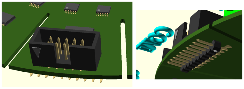
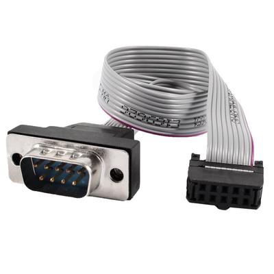
It might not be immediately obvious that a 2x5 box header is a standard RS-232 connector, but in fact it is almost trivial to make it so. This kind of connection was common back when desktop PCs had RS-232 serial ports. This header would be found on the motherboard or adaptor card, and a ribbon cable would be used to connect the box header to the DE9 on the rear panel of the PC. This is probably one of the easiest kinds of cables to make, as both connectors are squeezed onto the cable with an arbor press.
TTL Serial Pin-outs
Choosing the style of connector for TTL logic level signals was easier than selecting a pin-out. There is really no standard, almost everyone uses a different kind of connector. Even when the same connector is used, the pin-outs are invariable different from one system to the other. The closest thing to a de-facto standard is the 6-pin single-row terminal strip used by various modules from SparkFun and FTDI. One could be forgiven for thinking that two products, serving identical purposes, and using identical chips, would have the same pin-out. In fact, they don’t. Consider these two examples:
However, a review of their data sheets will show:
| PIN | SPARKFUN | FTDI |
|---|---|---|
| 1 | GND | GND |
| 2 | CTS | CTS |
| 3 | POWER | POWER |
| 4 | TXD | TXD |
| 5 | RXD | RXD |
| 6 | DTR | RTS |
I finally came up with an acceptable pin-out which I have based on Dave Yost’s rollover cable scheme. I’m calling it, for lack of a better term, a “Modified Yost” connector. I’ve kept the basic pin-out, but used a different connector. Instead of an 8-pin RJ-45 connector, I’m using a 10-pin terminal strip. The extra two pins are used to provide power to a target board, a function commonly found on these TTL logic level interfaces. And, of course, I’m using the connector for TTL and not RS-232 level signaling. The resulting pin-out is shown below, with the original Yost pin-out for comparison.
| MOD PIN# | SIGNAL | YOST PIN# |
|---|---|---|
| 1 | VCC | |
| 2 | RTS | 1 |
| 3 | DTR | 2 |
| 4 | TXD | 3 |
| 5 | GND | 4 |
| 6 | GND | 5 |
| 7 | RXD | 6 |
| 8 | DCD | 7 |
| 9 | CTS | 8 |
| 10 | VCC |
The advantage of this pin-out is the same as the original Yost cabling system, though easier. If one needs to change from DTE to DCE, you just turn the mating plug around. What I don’t like about this is that I’ve never seen this pin-out on any embedded system. But I’ve concluded that almost any pin-out will require the user to move around individual wires on the target end of the cable. So I might as well use a convenient and sensible pin-out on the Squid side. It is expected that a most Serial Squid users will keep a 10-pin to 6-pin SparkFun/FTDI cable handy, and fall back on a 10-pin to individual pin sockets cable when necessary.
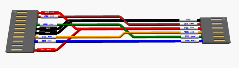
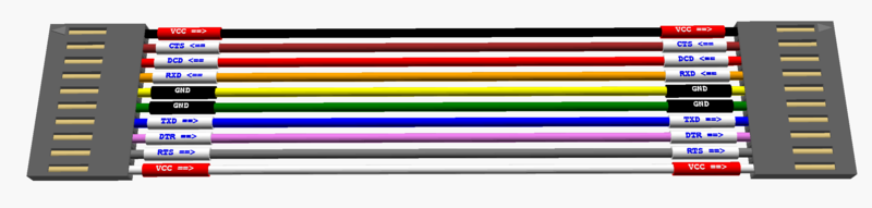
Modified Yost 1x10 to Sparkfun (top) and FTDI (bottom) 1x6 cables:
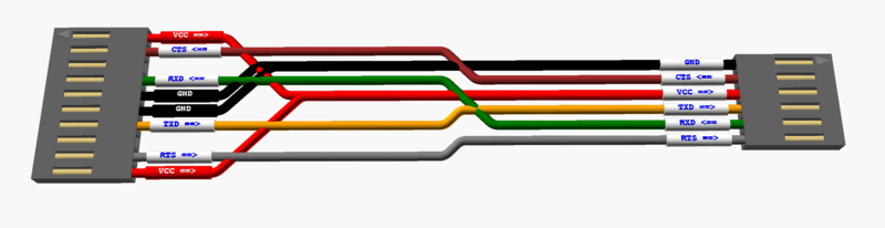
Modified Yost to Modified Yost 1x10 cable:
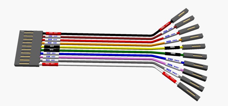
Modified Yost to 1x10 to individual pin sockets:
RS-422/485 Balanced Serial
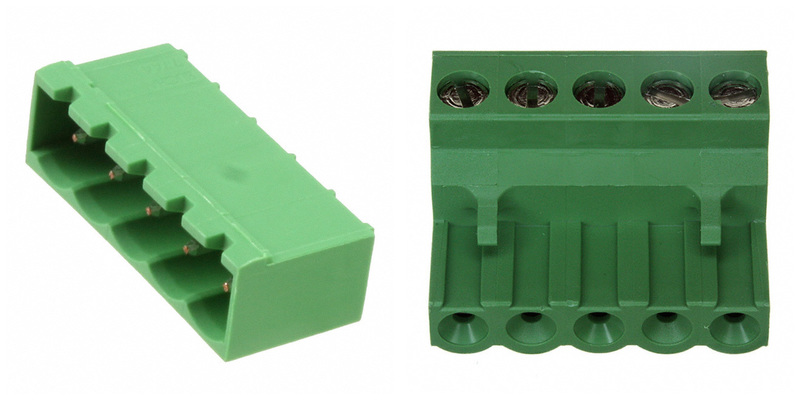
The choice of connector for the RS-422 / RS-485 connector wasn’t quite so difficult. One of the most common interfaces for these signals is a simple terminal block. There are various styles possible, but I chose a pluggable terminal block. This keeps the size down on the PCB, allows the flexibility of bare wires for matching up pin-outs, and the convenience of a pluggable connection.
And while there isn’t a standard pin-out, quite a number of devices on the market are very similar. I’ve picked that seemed logical, although I’m open to revisit this as I learn more. See the below table.
| PIN# | SQUID | Prod#1A | Prod#1B | Prod#2 | Prod#3 |
|---|---|---|---|---|---|
| 1 | TRDA(-) | T- | T+ | TRDB(+) | TDA(-) |
| 2 | TRDB(+) | T+ | T- | TRDA(-) | TDB(+) |
| 3 | RDA(-) | R+ | R- | RDB(+) | RDA(-) |
| 4 | RDB(+) | R- | R+ | RDA(-) | RDB(+) |
| 5 | GND | GND | GND | GND | GND |
Legend:
- Prod#1: Serialcomm Model CON-422-PE9 (datasheet). #1A=regular, #1B=sealed
- Prod#2: Black Box Model IC820A (datasheet)
- Prod#3: B&B Electronics Model 4WSD90TB (datasheet)