What is a serial squid?
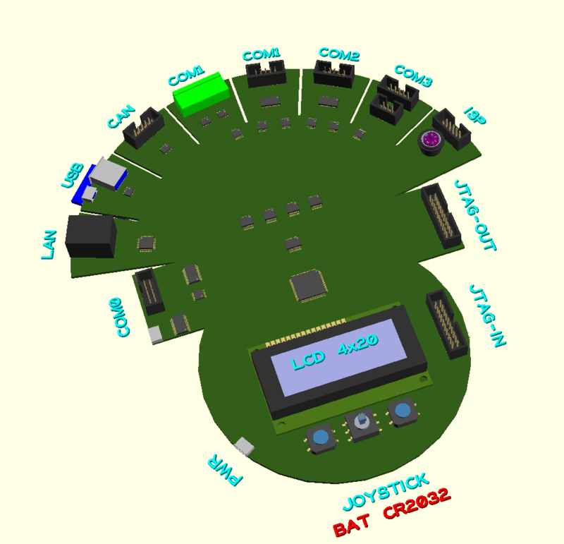
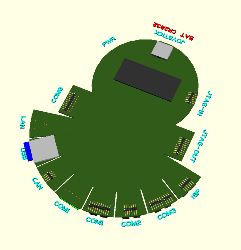
The Serial Squid is a serial communications hub, useful for the development and testing of embedded systems projects. It can be operated stand-alone or remotely. True to its namesake, the Serial Squid has eight arms, two tentacles, and a round body. The I/O ports are found on the appendages, and the user interface and other supporting circuitry is found on the head and main body.
Based on the NXP LPC1769 Cortex-M3 microprocessor, it supports nearly every serial interface found in today’s embedded systems. Useful applications include lab development, field operations, data logging, factory test fixtures, and education.
What’s under the hood?
The main microprocessor powering the Serial Squid is from the popular NXP LPC17xx Cortex M3 family, specifically, the LPC1769. It is identical to the common LPC1768, but for the addition of an Ethernet interface. The wide range of build-in peripherals in this family provide all the serial interfaces we need, requiring only minimal external support circuitry. A wide variety of sample code and drivers for this microprocessor is available from NXP, and from the large Cortex M3 developer community.
In addition, a small Microchip PIC is a support microcontroller to handle a few
auxiliary tasks. It does a few miscellaneous I/O functions, primarily because
I’ve exhausted the available pins on the LPC1969. It also provides
non-volatile EEPROM storage, and manages the configuration of the various I/O
ports. The PIC I’ve selected is a modern version of the very popular and long-running PIC16F628A, the PIC16F1847. This new PIC is
pin-compatible with the 628A, and provides a number of new functions which make
it very attractive: low cost, familiarity, and powerful features.
What serial protocols?
As for the serial I/O ports themselves, most common serial formats are supported. These ports are distributed among the squid’s legs, and grouped into logical com ports such as COM0, COM1, etc.
- RS-232
- RS-422/485
- TTL serial
- I2C
- SPI
- CAN
- USB
- Ethernet
- PS/2
- PIC ICSP
- AVR
- JTAG
In fact, if you bounce this list of interfaces against the list of serial peripheral blocks provided by NXP, with one exception, every interface is made available to the user, along with some additional ones made possible by bit banging. The one exception is the I2S serial sound interface. This is an interface I’ve never encountered in my experience, although I’m open to suggestions to include it if enough users think it is important1.
How does the user control it?
The user interface is simple but adequate for the envisioned applications. A 5-direction joystick is provided for menu navigation, along with two separate general purpose push buttons. Information is presented to the user via the 4x20 character LCD display module, a magnetic buzzer, and assorted indicator LED’s around the circuit board. In addition, the Serial Squid can be controlled over the console serial port COM0, the PS/2 keyboard interface, Ethernet or USB. Indeed, if an application calls for it, any of the available serial interfaces could be used for control.
How is it powered?
The Serial Squid is powered from a standard +5VDC micro-B USB power adaptor. The intention is to take advantage of existing equipment the user may already have, or can easily purchase. There is no need to reinvent the wheel. If needed, smartphone external battery packs can be used for field operations2.
How is it programmed?
The Serial Squid’s LPC1769 can be programmed in several ways. The primary method is over a standard ARM 20-pin JTAG port or over the COM0 serial port. USB or Ethernet port programming is also possible if suitable bootloader firmware is installed. The PIC is programmed over a standard 6-pin ICSP connector. Two miniature right angle push buttons are provided for boot control. The RESET button performs a hardware reset of both micro-controllers. A second ISP-MODE button will put the LPC1769 into ISP mode on boot-up, and is also used to select which of the three COM0 connectors to use for ISP: the USB virtual serial port, the RS-232 DE9, or the TTL-serial pin connector.
Anything else?
A removable SD card is provided for the storage of data and scripts. A small EEPROM store is provided for configuration and application data. A real-time clock crystal and backup battery provides a clock and calendar.
How is it designed?
As much as possible, I’m designing the Serial Squid to be an open project, designed using open tools. The circuit board should be easy to assemble and repair by hobbyists (no BGA packages, for example). Standard circuits from reference designs or proven projects are used, and much thought has gone into selecting connector styles and pinouts. The design has been done using free and/or open source tools:
- KiCAD for schematic and PCB layout
- Draftsight for 2D drawings
- OpenSCAD for 3D drawings
- Libreoffice Calc for spreadsheets (BOM, pinouts, etc.)
- Libreoffice Draw for diagrams (block diagram, etc.)
- GNU compiler tool chain
- PIC compiler and tool chain is TBD
I’m also striving for platform independence on this project. So far, I’m able to use all the above tools on Windows, Linux and Mac OS. Use and design of the Serial Squid will be detailed in future posts.
The repository for the Serial Squid project has been started on Github and will be periodically updated as the design wraps up.
Footnotes
-
A brief review of the schematics and data sheets suggests that the I2S signals could be used if it was acceptable to preempt the SD Card interface and two of the four handshaking lines associated with the console serial port, COM0. I’ll have to research the I2S connectors and see if there is room on the board. ↩
-
The baseline circuit schematic for the power supply is a simple starting point. Expect additional tweaks to deal with the USB specs for power charging over the micro-B connector. ↩