Not surprisingly, when I returned these units to be installed in the real model train layout, they didn’t perform very satisfactorily. The variation of times from one engine to another engine was unacceptable. So these units were replaced by a new design: the Heathcote SA5-S Controller.
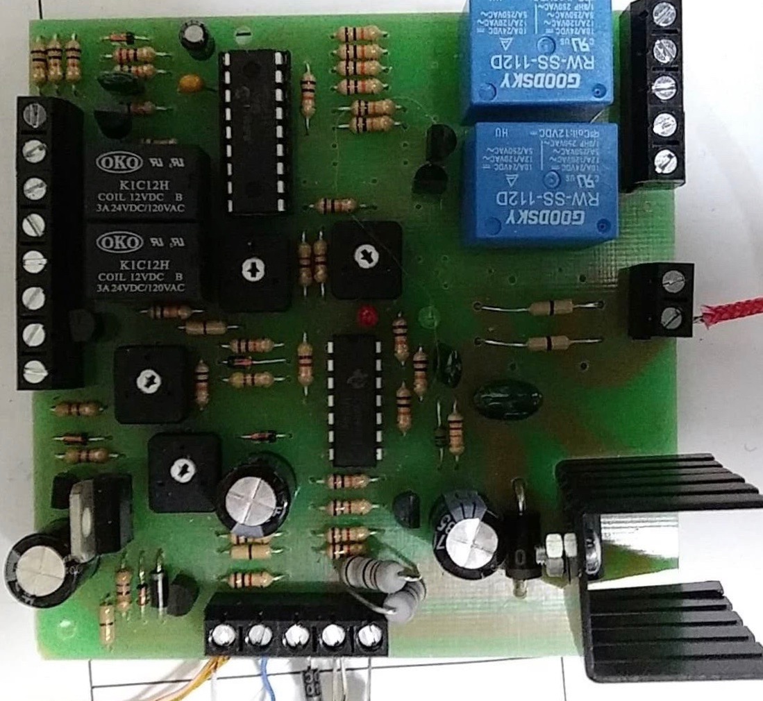 Heathcote SA5-S Controller Printed Circuit Board Assembly
I haven’t analyzed this unit, but it reportedly works better. It is still basically an analog design, but apparently it overcomes some of the issues of the first unit at the cost of additional circuit complexity. There was one documentation concern regarding installation of the unit.
 SA5-S Wiring Diagram from the Manual
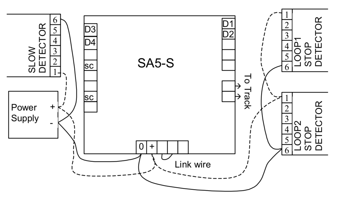
 SA5-S Connection Diagram from the Manual
Despite the detailed manual, it wasn’t initially clear to us how it should be connected, specifically with regards to if / how many isolated track segments are needed. And the final answer was a little counter-intuitive at first.
It turns out that many turnouts operate mechanically and electrically like a switch. As a result, no isolated track sections are required. There are some turnouts which don’t behave like this, and that’s why isolated sections are shown in the manual. The manual didn’t have all the connections in one place, so I made an overall drawing showing the complete installation pdf-version
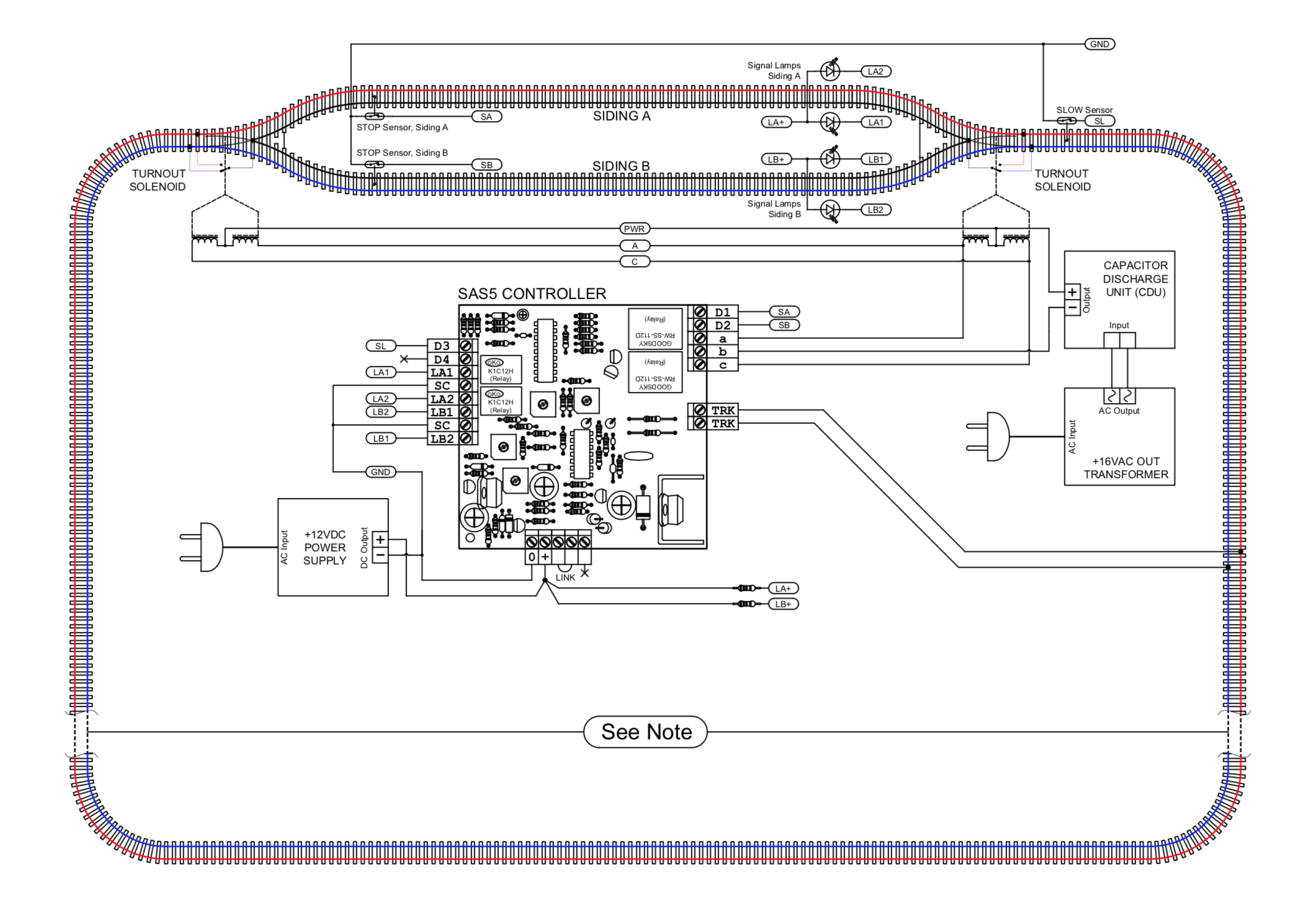 Redrawn SA5-S Setup Diagram
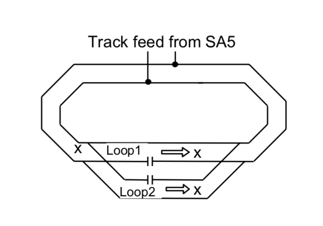
Regarding the note shown on the diagram… the manual shows a single loop. But many installations don’t use a loop, or rather, have multiple loops. After some thought, we realized that the loop wasn’t important. More accurately, we should think of it as a siding controller.